Arduino APRS Tracker
An APRS tracker is easy to build these days.
I had decided to build one for portable use (plan is to be used on hiking, but also in my car) powered from Lithium Ion battery and with all components running on 3.3V. Transmit of APRS messages is done through a UV-5R.
The tracker is powered from my favorite Panasonic NCR18650 3400mAH through a MCP1700-3302E LDO regulator, and has plenty of juice for daily use.
GPS is a Adafruit Ultimate GPS Breakout – 66 channel w/10 Hz updates (https://www.adafruit.com/product/746) not that i need 10 Hz, 1 Hz update is more than enough but i had in stock from a different project, so why not ? (i love it)
Arduino is a Pro Mini 3.3V 8 MHz (actually a clone of Deek-Robot Pro Mini)
Update
Bought a Kenwood cable to avoid the mess with the 2.5 and 3.5 mm audio connectors
BIG FAT WARNING : There is no load disconnect for the battery while charging. DO NOT CHARGE AND USE IT. The charging of the battery will never finish, resulting on explosion, fire etc. YOU HAVE BEEN WARNED
https://www.aliexpress.com/item/DIY-2-pin-4-Wire-Speaker-Mic-Cable-Spring-Line-for-Baofeng-UV5R-Kenwood-TK370-Linton/32734963747.html
Added also a TP4056 Lithium Cell Charger Module with Battery Protection to charge it through USB.
I have started working with the schematic of MicroModem (http://unsigned.io) but i have modified LibAPRS to make it work.
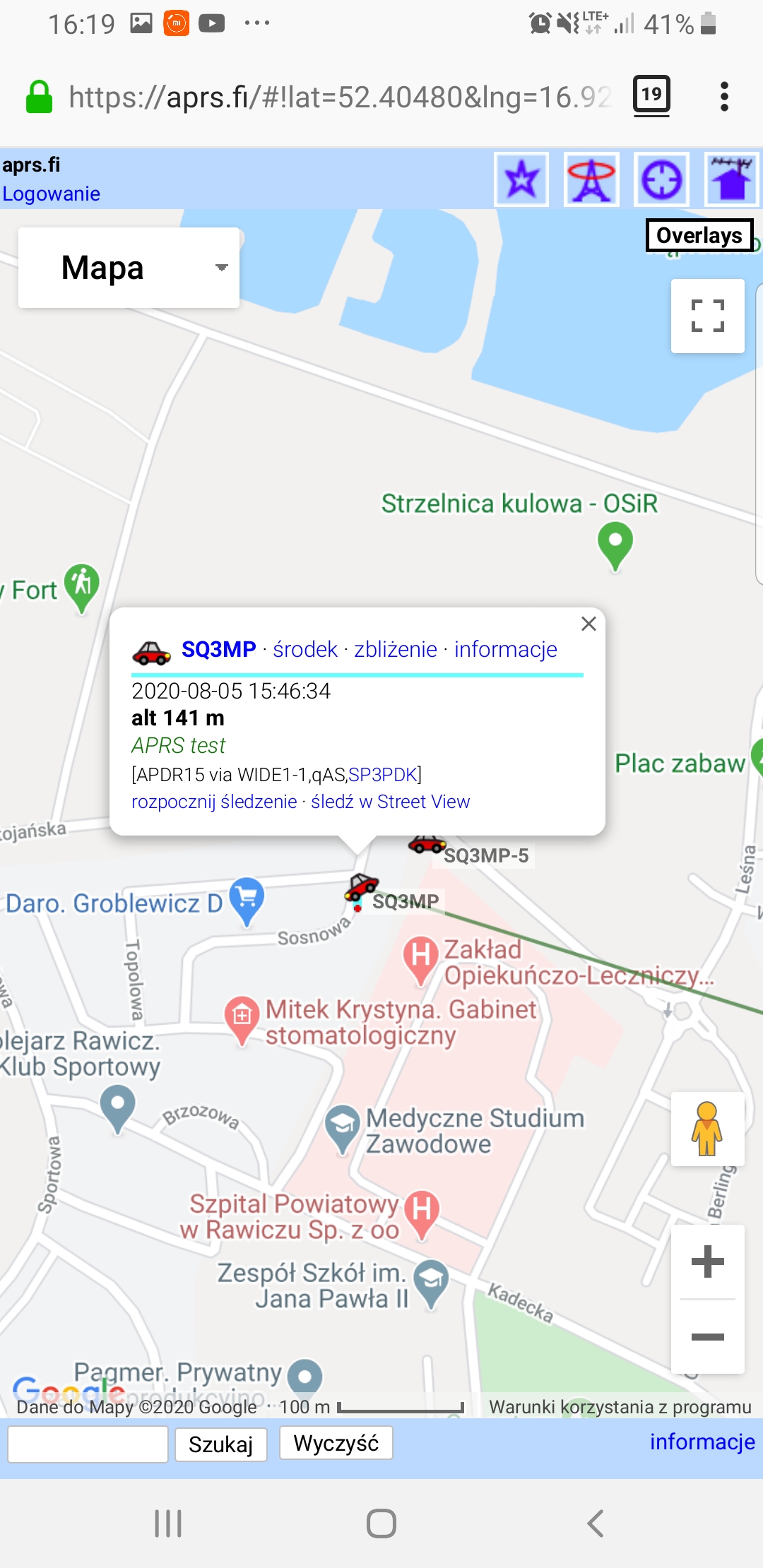
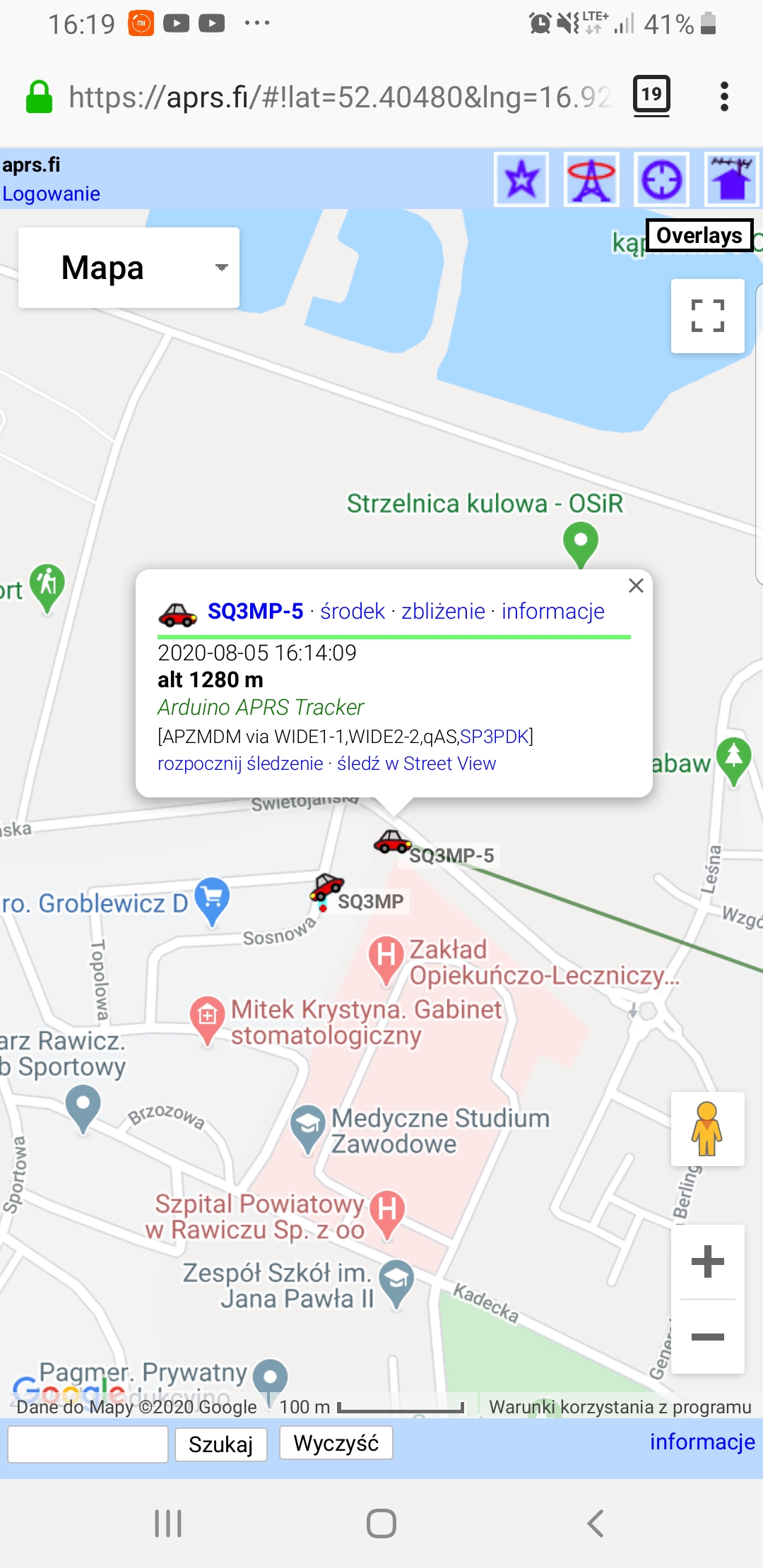
As long as GPS has a FIX it submits my location every two minutes and i have a button for a single shot APRS update. SmartBeaconing support is included (check the relevant branch on github)
The idea is to create a complete unit with a DRA818V with USB charging.
DRA818V is still on my desk… i have “trouble” designing a good low pass filter for VHF.
Schematic (breadboard version)
Remember power supply needs to be 3.3V
Arduino APRS tracker schematic (for the breadboard version)
Documentation has not been finalized yet and i use multiple libraries making it a bit difficult to handle everything
I have uploaded my working version to github
https://github.com/billygr/arduino-aprs-tracker
Remember to change the APRS_CALLSIGN to your call sign
You will need these libraries
libAPRS (modified) https://github.com/billygr/LibAPRS
TinyGPS http://arduiniana.org/libraries/tinygps/
SimpleTimer is included in the project (delete your version from Arduino/Libraries)
PCB
Oh yes !!! We do have also PCB ready credits to aronaut. Thank you !!!
https://github.com/billygr/arduino-aprs-tracker/tree/master/APRS-Tracker_KiCad
Bill of Materials (breadboard version)
R1 1K
R2 2K2
R3 3K9
R4 8K2
R5 270
R6 10K trimmer
R7 1K
R8 10K
C1 100nF
C2 4.7uF/16V
1x GPS Module
1 x push button
1 x Arduino Pro Mini 3V3 8MHz
Q1 2N2700/BS170
For using without an external power supply
1 x Panasonic NCR18650 3400mAH (or your favorite 18650)
1 x 18650 socket
1 x MCP1700-3302E
Bill of Materials (PCB version)
Includes the 18650 socket+TP4056
https://github.com/billygr/arduino-aprs-tracker/tree/master/APRS-Tracker_KiCad
Billy my ideas for perfect baloon tracker in your project
Altitiude above sea level in APRS report
2x BME280 sensors in APRS telemetry
Battery voltage in APRS telemetry
Hello,
Could I buy PCB and how much does it cost?
Best Regards 73!
Stan hi,
I don’t sell boards unfortunately , you can use the gerber files and order directly if needed
SV1QFV
Hi!!
thanks for you work!!
recently i am worked in your program and implement the smartbeaconing function.
https://github.com/fnabarlats/arduino-aprs-tracker/tree/newfunction
Also implement a new functions on LibAPRS to send Course and Speed in aprs data.
https://github.com/fnabarlats/LibAPRS/tree/newfunction
thanks for sharing your work, this has been very helpful. And Sorry for my english!!!
73! LU5EFN
Thank you Frederico, i will review both over the weekend and merge them.
Many thanks for your work !!!
73 SV1QFV
Federico how about to add altitude report to aprs ?
It’s already there, try it it you can check it on aprs.fi
I try to upload your heavy job to my board but after verification I receive info : “APRS_setSpeed was not declared in this scope”
Please download again the LibAPRS i just committed the missing fix
Dear Bily
I tested the altitude report on tracker and I have small problem
APRS frame sent from phone via aprdroid show me on 141m and “Billy tracker” show me on 1280m.
Is there some possibility of altitude calibration or there is some error in library ?
http://imgurl.pl/img2/screenshot20200805-161949firefox_5f2fc3037dce1.jpg
http://imgurl.pl/img2/screenshot20200805-161943firefox_5f2fc355e4885.jpg
Please see screens
Hi,
Can you please check the serial output ? It spits out the altitude from GPS on both meters and feet. If it looks ok then the issue is on the transmission/conversion to APRS message
Thank you !!!
Checked already the altitude on ublox software and GPS connected to the laptop. On laptop gps shows correct altitude
I mean the serial output of the Arduino what is the altitude that it displays ?
Tell me please, I put your firmware on the tracker based on Arduino Pro Mini 3.3V 8 MHz and gps module NEO-6M-0-001, the tracker aprs transmits, but for some reason the SmartBeaconing system does not work, something in your firmware needs to be enabled or the GPS module not suitable for work. I put the firmware from here: https://github.com/billygr/arduino-aprs-tracker/blob/master/arduino-aprs-tracker/arduino-aprs-tracker.ino
I can not figure out how to make it work, the coordinates are transmitted by the tracker when updating after 2 minutes. And when turning, turning and changing speed, nothing. I will be grateful for your help.
Hi Roman,
Smartbeaconing is on this branch
https://github.com/billygr/arduino-aprs-tracker/blob/smartbeaconing/arduino-aprs-tracker/arduino-aprs-tracker.ino
Try it
Hi Roman,
Use the Smartbeacoing branch or this link directly
https://github.com/billygr/arduino-aprs-tracker/blob/smartbeaconing/arduino-aprs-tracker/arduino-aprs-tracker.ino
Billy please see, photo of com monitor
https://www.dropbox.com/s/8quwpisexb7dngd/20200818_161504.jpg?dl=0
https://www.dropbox.com/s/lju1huafz84wmbv/20200818_163423.jpg?dl=0
Ublox software – the same gps
Hi,
I just checked both pictures, there is no conversion in my code , we get the output directly from TinyGPS.
Could you please be so kind and do a test the test_with_gps_device.ino from the TinyGPS library ?
73, SV1QFV
Will check during this weekend, sorry for delay, familiy + work ..
Nice post,thanks for sharing
Visit Us
Billy only this “data” I get from GPS, I don’t know what I have done wrong
https://www.dropbox.com/s/kc801mzg6wydk0l/gpstest.JPG?dl=0
Ok, I found mistake
https://www.dropbox.com/s/60tdvd4ujomqc60/Gpstestok.JPG?dl=0 – here is correct report
And the altitude is not reported as around 60 m ?
Yes, GPS reports 60m – it is correct data, but APRS report each time 1200m
Billy
According Your next aprs nice project … ( not possible to comment there )
Not better use diferent low pass filter ? http://599.cz/view.php?cisloclanku=2018082201 – please see – easy to make and prepare. LFCN-160+ very difficult to get ( expensive item + expensive delivery ) – If You have cheap source for it please let know
Please consider
Regards
You are absolutely right, thanks for the comment and the filter option !!!
Great project! Is there room for a “busy detect” mechanism?
Yes, i have it on my todo list !!!
Hola te consulto cada cuantos minutos emite la posicion o hoy que oprimir el boton para que lo haga, saludos LU7FDV
From google translate: It emits the position every two minutes unless you use the smartbeaconing https://github.com/billygr/arduino-aprs-tracker/blob/smartbeaconing/arduino-aprs-tracker/arduino-aprs-tracker.ino branch
Hola si lo hago con arduino nano hay que cambiar algo en el programa ?saludos LU7FDV
No change, just be careful with the pinout
Hi, Billy
From your Arduino code, we didn’t see any code relevant to pin D4 to D7. Can you pls explain how your code work?
It’s part of libAPRS, a small DAC is being implement on PORTD relevant code on https://github.com/billygr/LibAPRS/blob/master/AFSK.cpp
Thanks Bily!
Hi Billy,
I had a read on AFSK. but not sure what lines of code relates to D4 to D7. Can u pls explain?
Hi Billy,
I had read AFSK but cannot find lines of code relevant to D4 to D7. Can you pls explain a little further. Thanks!
Hi,
Line 471/473 in the AFSK file
Billy
Thanks Billy
I try to upload the sketch you provided with FTDI232.
It gives the following upload error. How can this problem can be fixed?
avrdude: stk500_recv(): programmer is not responding
avrdude: stk500_getsync() attempt 1 of 10: not in sync: resp=0xd5
avrdude: stk500_recv(): programmer is not responding
avrdude: stk500_getsync() attempt 2 of 10: not in sync: resp=0xd5
avrdude: stk500_recv(): programmer is not responding
avrdude: stk500_getsync() attempt 3 of 10: not in sync: resp=0xd5
avrdude: stk500_recv(): programmer is not responding
avrdude: stk500_getsync() attempt 4 of 10: not in sync: resp=0xd5
avrdude: stk500_recv(): programmer is not responding
avrdude: stk500_getsync() attempt 5 of 10: not in sync: resp=0xd5
avrdude: stk500_recv(): programmer is not responding
avrdude: stk500_getsync() attempt 6 of 10: not in sync: resp=0xd5
avrdude: stk500_recv(): programmer is not responding
avrdude: stk500_getsync() attempt 7 of 10: not in sync: resp=0xd5
avrdude: stk500_recv(): programmer is not responding
avrdude: stk500_getsync() attempt 8 of 10: not in sync: resp=0xd5
avrdude: stk500_recv(): programmer is not responding
avrdude: stk500_getsync() attempt 9 of 10: not in sync: resp=0xd5
avrdude: stk500_recv(): programmer is not responding
avrdude: stk500_getsync() attempt 10 of 10: not in sync: resp=0xd5
Pls do not worry about question. Problem solved!
Hi Billy,
With GPS module, I use a module as GY-NEO6MV2. It works well with Arduino UNO.
But it doesn’t work with Arduino Promini 3.3V.
Can you pls suggest how to solve this problem? I noticed the model of GPS you used in your project. Wonder if any particular requirement is needed and alternative GPS meed the need of circuit.
Thanks
Robbie
Hi,
Ensure that RX/TX are correctly attached and modem is on the correct speed, there is a fellow ham that reported that it Arduino promini works also this module.
Can you try with the demo program of TinyGPS library ? If it works there it will work also with the APRS tracker
Billy
Thanks Billy. Tested it works with 3.3v
hi. how can i order a pcb? can you give me a site? how cost?
SV7PKL
Gerbers are provided on github, a new PCB will be available later this month. Costs are around 10 $ directly to the PCB manufacturer
i order 10 pcb`s with shipment 12 euro.
the capacitors is tantalum or i can use single?
73 SV7PKL
Tantalum capacitors, 73 SV1QFV
Αν βάλω κεραμικούς υπάρχει πρόβλημα? Οι τανταλίου γίνανε σπάνιοι!!!
Μπορώ να χρησιμοποιήσω κεραμικούς πυκνωτές διότι οι τανταλίου είναι σπάνιο είδος?
hi. i load the code to arduino and i put it in pcb. nothing happend. i try to press the beacon button nothing again. any idea? thanks.
73 SV7PKL
Hello, it happened to me. Do you have a GPS signal? the flat neo 6 should flash the led. Greetings
Connect to the serial of Arduino. If you don’t have any output you used a 16MHz version. You will need a 8MHz / 3V3 Arduino
το συνδεσα στο serial και οταν παταω το κουμπακι στο arduino μου εμφανιζει Arduino APRS Tracker. για να λειτουργησει πρεπει να βρει στιγμα το gps ή για δοκιμη δεν χρειαζεται?
i connect to serial and when push the button on arduino write “Arduino Aprs Tracker”. the gps must fix the sats to test the tracker?
if there is no GPS fix nothing happens, it will wait for a fix first
Hello, I saw that some friends had the same problem that appears to me. The altitude shows 1280m, when I am currently at 100m. For what is this? can it be corrected? Thank you
Hello, I saw that some friends had the same problem that appears to me. The altitude shows 1280m, when I am currently at 100m. For what is this? can it be corrected?
Is the sending time between packets fixed, or does it vary according to the speed of movement?
Thank you
If you use the SmartBeaconing version the sending time of packets depends on your speed. As for the altitude difficult to explain/debug it, can you please send me two three lines of the serial output ?
Τελικά στέλνει μια χαρά με το BAOFENG. Άλλαξα το gps και δουλεύει μια χαρά. Μπορώ να αυξήσω το χρόνο εκπομπής επειδή το δοκίμασα με το vhf module SA828 και αργεί λίγο να ανοίξει με αποτέλεσμα να μη στέλνει όλο το πακέτο.
73 SV7PKL
Ready in its box with VHF module SA828. It works perfectly with a digipeater. The test is left how long the battery lasts and if necessary another will be added.
https://photos.app.goo.gl/9ouNCbGFfqvTaxrMA
https://photos.app.goo.gl/uA1LpPoeA3H2r2JW6
73 de SV7PKL
Ready to box.
https://photos.app.goo.gl/r6pRReKijHFCRASQ8
https://photos.app.goo.gl/qdB6c73RhcnvAzii7
73de SV7PKL
There is a significant bug in the NMEA conversion code that does not put a leading zero for longitudes less than 100. This causes the packet to be rejected or the position information not to display in most APRS decoders, including the Yaesu FTM-300, APRSIS and APRS.fi.
I solved this by borrowing a NMEA converter routine from another project and changing the flat and flon variables to “long” from “float”, then calling the update lat/lon routine version written for long variable position variables. The new NMEA conversion routine also requires “long” position variables.
I also removed the display routines for smaller code size and a less battery-hungry profile.
Works fine now. The rest of the code is excellent.
Thanks for letting me now , could you please file it under the github page ideally with your proposed fix ?
Can you explain the reasoning behind the different values for the audio output resistors?
Hi,
It forms a basic DAC (actually a Binary Weighted DAC) to create the audio signal
Yours,
Bill
Hello, We are building a CANSAT and trying to implement an APRS System for tracking it. I would like to know how can we do that using Arduino and how should whole System should be tracked from the ground station. would require some help.
It’s really nice and meaningful. It’s really cool blog. Linking is very useful thing. you have really helped lots of people who visit this blog and provide them useful information. Thanks for sharing, let’s Visit Us
HI,
Thank you for your program it is wonderfull.
Its works very fine.
Now the question HI.
You use pin 13 ( internal led ) for checking that TX is done. I would like this on a other pin pe pin 2 . I can’t find where i have to do this in the program .
Can you help me?
’73 John
Hi John,
Its a bit complicated.
LED is defined on https://github.com/billygr/LibAPRS/blob/master/device.h line 32
#define LED_TX_PIN 5
Pin 5 is the PB5 on PORTB.
You will need to change the #define LED_PORT PORTB to the relevant PORT for the Atmega328 and the pin accordingly, use this pinout as a reference
https://upload.wikimedia.org/wikipedia/commons/c/c9/Pinout_of_ARDUINO_Board_and_ATMega328PU.svg
73,
Billy
Hi Billy,
It work’s.
Thkn’s.
Excellent service.
’73 John
It needs a bit of code cleanup 🙂 . many thanks for your comments
thanks for sharing
I followed all the breadboard schematic but I can’t get the module to trigger signal to my walkie. anyone can share the experience? GPS LED is blinking.
Mike can you check that is a change on the PTT while you transmit ?
Hi Billy, I’ m planning to build a simple tracker and I found you project, which is exactly what I need to do that. Since I’m very noob in knwoledge to program Arduino, but I´m ok in electronics, I want to ask you if in your project it´s possible to retrieve the TX and RX data BEFORE they’re converted to audio AFSK, to connect it to a external modem IC (like the TCM3105, AM7910, etc) intended for more robust transmission. Have you and idea to do such that?
Thank you very much in advance!
Leandro
LU8DOI
Hey ,
I have read the pdf of TCM3105 but i don’t understand what is the expected input of TX (i assume analog but in what format ?)
LibAPRS implements the AFSK modem in software , which means it needs a complete rewrite. You can have a look at AFSK_dac_isr (in LibAPRS/AFSK.cpp)
What i am saying here is that if you can understand what is the analog input needed to have a proper APRS message it could be possible.
73
Hi!
Is there a way to specify how long into the 2 minutes the packet is started? So that several of these running on GPS time could be programmed to transmit at different times and avoid packet collisions?
Thanks,
Joe G0EVB
Hey,
I do understand the need but it is not implemented , ideally we should monitor the frequency and then decide if we should transmit or not.
Its not random but it is 2 minutes after you got a GPS fix, you could add some randomness on the 2 minutes +- 10-15 seconds
73
Hi,
Thanks for the response. Would that be achieved by altering line 97 to be e.g. 1.9 instead of 2?
aprs_update_timer_id=timer.setInterval(1.9*TIMER_MINUTES, setAprsUpdateFlag);
73 de G0EVB
That would do it, alternative change the #define TIMER_MINUTES 60L*1000L value