I wanted an interface to try the digital modes (PSK31,RTTY,JT65, SSTV,WSPR etc) without investing a huge amount of money for a commercial one.
I came across to the work of the work of g4ilo SK (http://www.g4ilo.com/usblink.html) and decided to build one. All credits goes to him.
Bill of Materials
1xUSB sound card (bought mine on ebay for a couple of euros) has VID 0D8C PID 013C (0D8C:013C). Search for 7.1 USB sound card on ebay
1x10K 1/4Watt
2x4K7 1/4Watt
1x47K 1/4Watt
1x330K 1/4Watt
1x1K trimmer
4x1uF tantalum capacitors
3x1N4148
2x2N3904
1xRed LED 3mm
1xUSB type B connector
1xOn/Off switch (can be used to disable VOX operation)
1xProject Box of you choice
1xSmall proto board
1xConnector for your receiver (i used the 13 PIN DIN for my ICOM IC-718)
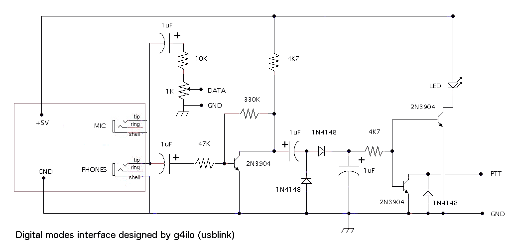
Schematic
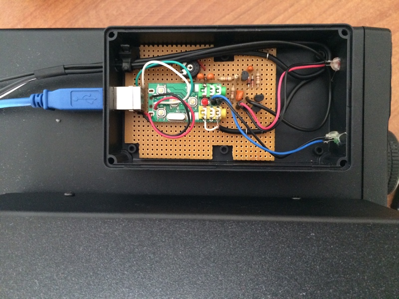
Project notes
Removed the case of the sound card and the USB connector and replaced it with the USB type B.
The green led of the sound card was connected in front of the box (pulses when the card is in use)
The red led of the sound card is ON only when you have muted it. So there is no need to desolder it from the board.
Adjust the trimmer around mid position
Finished product
I already used it for QSO in PSK31/JT65 and SSTV successfully.
Leave a Reply