I have used a couple of ESP8266 boards in the past mainly NodeMCU, D1 Mini and Adafruit Feather.
In the long run and for some projects a wanted something simpler (not smaller), and iron out the mess with the different pinouts/functions per pin etc (my personal view of course)
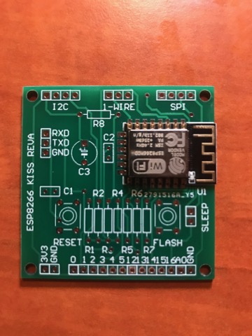
So here we go: The board is called ESP8266 KISS.
Plain old through hole components, NO SMD used
NO USB Interface. Usually in the place i put the board there is not way to attach a USB cable later on…
Just the basics
UART interface
RESET and Flash Button
1-WIRE header
SPI header
I2C header
GPIO header
9 out of 10 times i need a header to connect a peripheral like I2C/SPI/1-WIRE so i have added them as a default.
I have omitted the auto reset functionality from this version since it requires more pins and the common RS232 to 3V3 TTL usual they don’t have them exposed
Schematic
PCB
The PCB is 2000mil*2000mils (around 5cmx5xm)
BOM
R1 12K
R2 12K
R3 12K
R4 12K
R5 12K
R6 220K
R7 100K
C1 100nF
C2 100nF
C3 470uF/16V
2x PUSH Button
1x ESP12-E
1x 40 pin female header
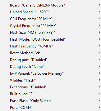
Programming
You can use the Arduino as a Generic Board
Settings below
To set the ESP8266 in programming mode
- Press the FLASH button and keep it pressed
- Press the RESET button, release the RESET button
- Release the FLASH button
Now it is in FLASH mode and it will stay there till you upload the sketch or press the RESET button again
Upload your Arduino sketch as usual
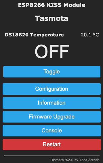
ESP8266 Tasmota
You can also tasmotizer the board and use it directly as Tasmota Device using the sensors firmware
Template for Tasmota
{“NAME”:”ESP8266 KISS”,”GPIO”:[1312,0,256,0,640,608,1,1,0,0,0,0,0,0],”FLAG”:0,”BASE”:18}
ESP8266 Tasmota with a DS18B20 sensor connected in the 1-Wire
Leave a Reply