An Antenna Analyzer is a nice tool for the shack, although not used constantly it’s the easiest way to test an antenna.
This is my fork/clone of the famous Antenna Analyzer from K6BEZ. I must admit that they are many different designs in the internet most of them based on the work of K6BEZ, resulting in different versions of Arduino code and different version of PC programs acting as the VNA software part.
The whole idea is build around a DDS board and you measure the forward and
reverse detector voltages from an SWR bridge at different frequencies, get the values returned to a PC and plot them on the screen.
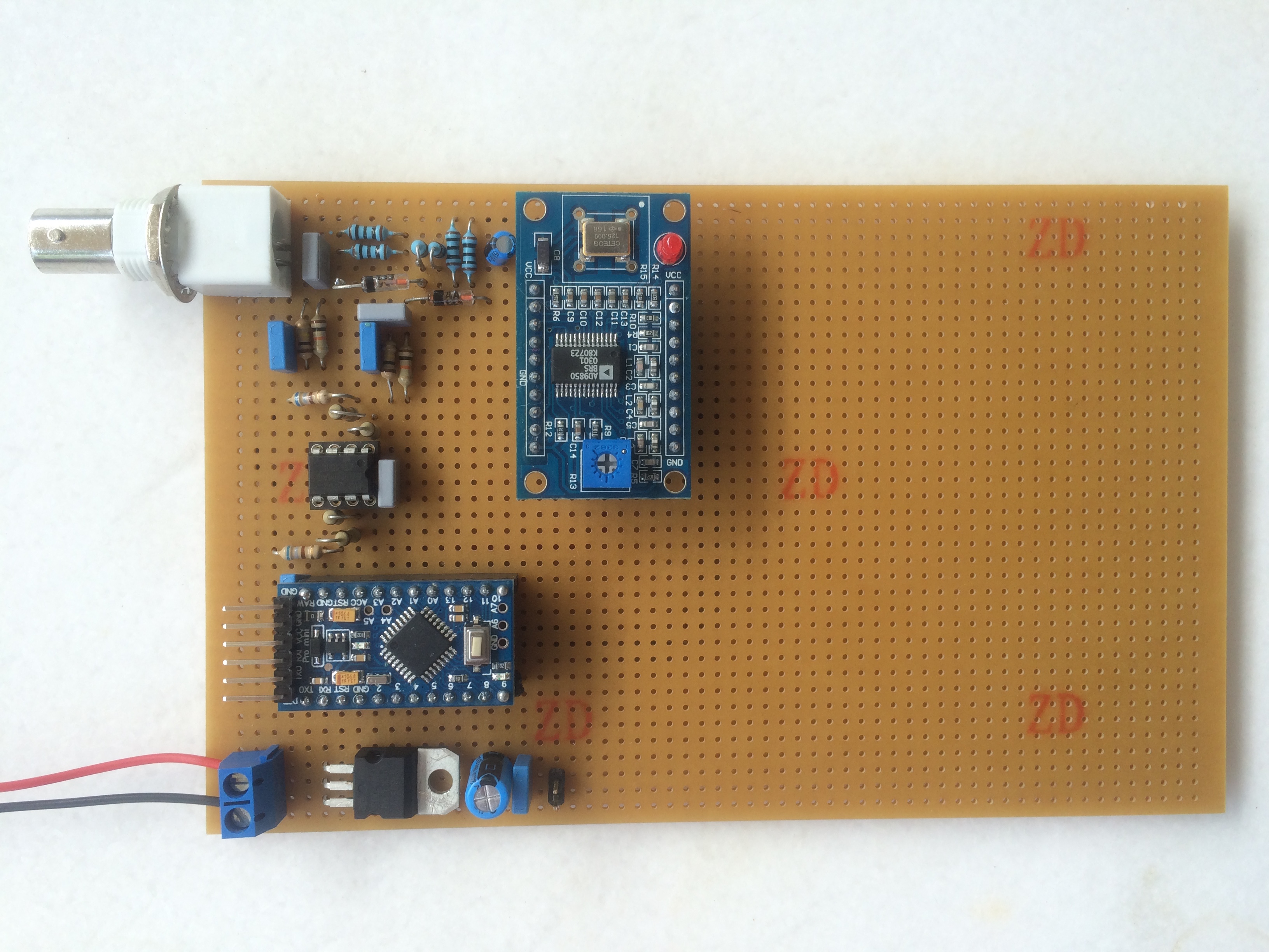
I have builded mine using an AD9850 board from ebay and an Arduino Pro Mini on top of a 10×16 PCB. A also have space for including an amplifier, Yes you need one if you want stable results. The sine wave output of AD9850 is not consistent across the bands. I have consider it version 1 and the next one will be with a AD8307 as a detector
 Click for bigger version
Changes from the original schematic
(http://www.hamstack.com/hs_projects/antenna_analyzer_docs.pdf)
In the picture above it looks like that there are two resistors in parallel but i have disconnected one of the legs.
The reason is that i found out that the reverse detector voltage was way to low so i decided to change the gain from the opamp (from 9,87 to 15,7 (5100/648)+1 -> (10000/680)+1))
Lessons learned: The germanium diodes break easily and yes i have been gentle
Testing the Antenna Analyzer
With the AD9850 working in a specific frequency let’s say 10MHz
do some measurements after you have build it to the following points
A0 REV -> INPUT pin 5, output pin 7
A1 FWD -> INPUT pin 3, output pin 1
With Antenna open or short circuit we should found voltage on the Rev pin
With a 50 Ohm terminator we should get a reverse voltage of around 0mV
Don’t expect that with a 100 Ohm resistor you will get a VSWR exactly of 2:1
Software
I have uploaded the relevant software for both the Arduino and the PC software to my github
https://github.com/billygr/antenna-analyzer
I don’t claim any credits/copyrights etc since it is not my work but i found it easily to work using git and have everything in one page. Credits to DG7EAO and DK2JK.
The code of K6BEZ is under the directory
https://github.com/billygr/antenna-analyzer/tree/master/DDS_sweeper modified in order to work with the program available in his dropbox link in the pdf here https://sites.google.com/site/k6bezprojects/antenna-analyser
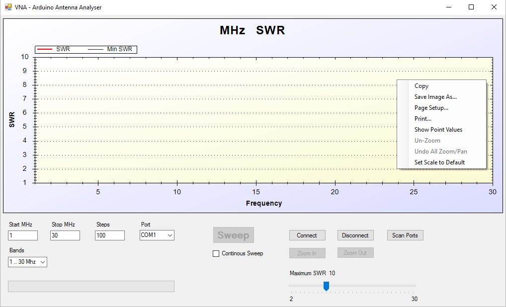
DG7EAO has created the VNA PC software in Visual Basic .Net
I have build an exe file of my own version here
https://github.com/billygr/antenna-analyzer/tree/master/VNA
Main changes
Screen shot
if you want to use it you will need to use the relevant DDS sweeper from DK2JK this time
https://github.com/billygr/antenna-analyzer/tree/master/dds_sweeper2_2 updated to work with the VNA. The AD9850 pinout is the same as in K6BEZ version because it dont want to change anything in my hardware.
Next steps
I decided not to create a PCB for this version it was just a proof of concept that it works. If you want one please use the version from dk2jk. [3]
I have the following as roadmap items
References
[1] http://www.hamstack.com/project_antenna_analyzer.html and https://sites.google.com/site/k6bezprojects/antenna-analyser
[2] http://www.dg7eao.de/arduino/antennen-analysator
[3] http://dk2jk.darc.de/arduino/index_arduino.html
The search for a DIY Antenna Analyzer remind me a bit the following comic from xkcd:

Leave a Reply