Digital Modes Interface

I wanted an interface to try the digital modes (PSK31,RTTY,JT65, SSTV,WSPR etc) without investing a huge amount of money for a commercial one.

I came across to the work of the work of g4ilo SK (http://www.g4ilo.com/usblink.html) and decided to build one. All credits goes to him.

Bill of Materials
1xUSB sound card (bought mine on ebay for a couple of euros) has VID 0D8C PID 013C (0D8C:013C). Search for 7.1 USB sound card on ebay
1x10K 1/4Watt
2x4K7 1/4Watt
1x47K 1/4Watt
1x330K 1/4Watt
1x1K trimmer
4x1uF tantalum capacitors
3x1N4148
2x2N3904
1xRed LED 3mm
1xUSB type B connector
1xOn/Off switch (can be used to disable VOX operation)
1xProject Box of you choice
1xSmall proto board
1xConnector for your receiver (i used the 13 PIN DIN for my ICOM IC-718)

Schematic
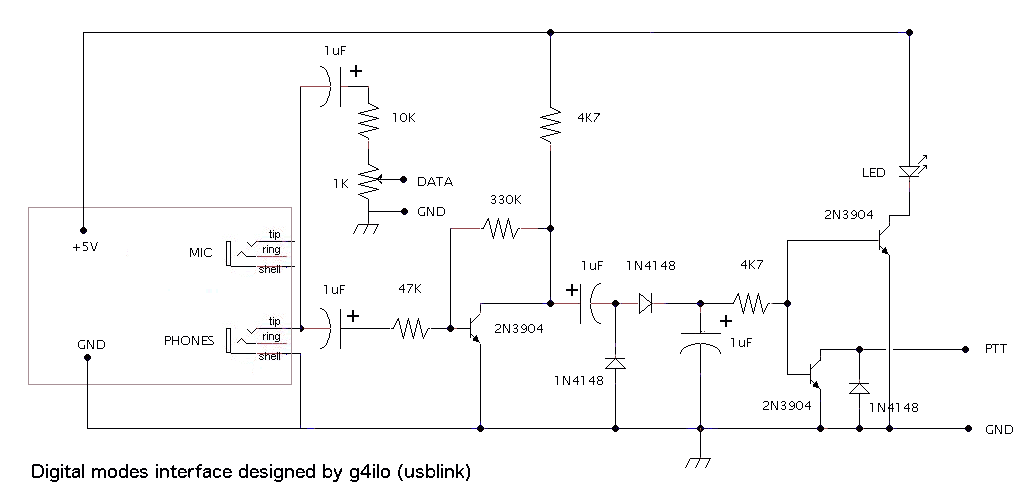
DIY Digital Modes Interface Schematic

Project notes
Removed the case of the sound card and the USB connector and replaced it with the USB type B.
The green led of the sound card was connected in front of the box (pulses when the card is in use)
The red led of the sound card is ON only when you have muted it. So there is no need to desolder it from the board.
Adjust the trimmer around mid position

Finished product
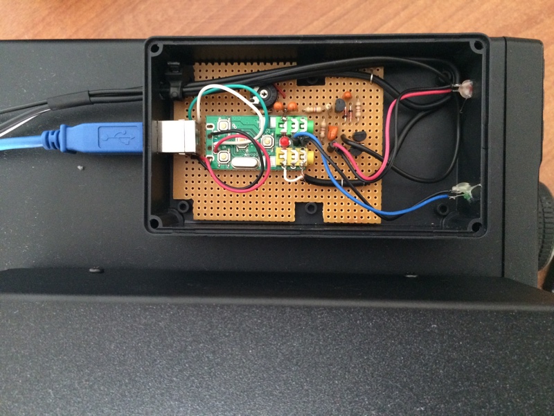
DIY Digital Modes Interface

I already used it for QSO in PSK31/JT65 and SSTV successfully.

Comments

8 responses to “Digital Modes Interface”

  1. Adrian Avatar
    Adrian

    How did you wire up the ic718 connector? I can’t make heads or tails of the manual

  2. billy Avatar

    Adrian hi,

    PTT -> PIN 3 + 7
    GND -> PIN 2
    RX -> PIN 12
    TX -> PIN 11

    And you are ready

    billy

    1. Adrian Avatar
      Adrian

      Thanks

  3. Abdurrahman Celebioğullarından Avatar
    Abdurrahman Celebioğullarından

    good day I liked this project very much. Which are the green led and red led connections on the scheme. Please help me

  4. Abdurrahman Celebioğullarından Avatar
    Abdurrahman Celebioğullarından

    Also where did you connect the Vox on-off switch in the diagram. Please help

  5. billy Avatar

    Hi,

    The USB sound card has two leds: Red and Green and are not visible on the schematic.
    You can omit if you want the LED of the schematic (it’s just an visual indication that the PTT is active)

    As for the VOX, the circuit creates a PTT from the sound output of the soundcard (=VOX).

    Connect the PTT to your transmitter and disable any VOX settings you have, it is not needed.

    73

    1. Jaime Eloy Avatar
      Jaime Eloy

      What are the connections for the Icom 706-MKIIG ?
      CU3AK
      Jaime Eloy

      1. billy Avatar

        You will need to locate you PTT,MIC/AF IN and GND on your Icom 706 accessory socket on the back of your radio

Leave a Reply

Your email address will not be published. Required fields are marked *