The project started as a timer for my PCB exposure box.
However since it almost look like a clock when i was designing it i added some clock features and the AVR Clock + Timer + (maybe i will add a temperature sensor was born).
It is split in two or if you add the power part 3 PCB
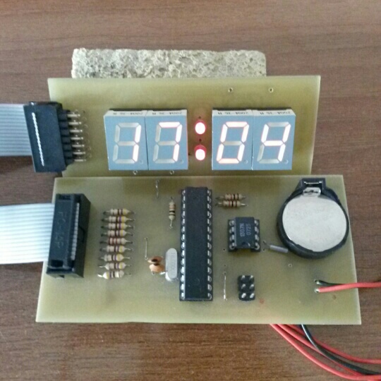
Display Board
4 Common Anode Seven Segments multiplexed
IDC 14 connector to the main board
2x3mm LEDs
Logic board
ATmega168
ICP 6 pins for the In system programming
IDC 14 connector to the Display Board
DS1307 with the CR2032 coin battery
Buttons
3 Button for the operation
Minutes Up
Seconds Up
Mode
Mode is selected between
Clock
Date
Timer Set (with the Minutes UP, Seconds UP)
Timer Ready (start with the Minutes UP, stop with the Second Up)
BOM
ATMega168
1x16MHz Crystal
2x22pf
1xDS1302
1×32768 Hz Crystal
4xSeven Segment displays CA
2xLED 3mm
2xIDC14 connectors
2x1K
1x10K
8X470
1×330
1xCR2032
1xCR2032 holder
Code on github
avr clock
Leave a Reply