I needed a frequency reference for my projects (gpsdo style) at 10 MHz
Fast forward:
There are two designs (and i have build them both) that work out of the box and are stable enough for my measurements
This one is FLL based https://www.instructables.com/id/GPSDO-YT-10-Mhz-Lcd-2×16-With-LED/
This one is PLL based
https://www.eevblog.com/forum/projects/lars-diy-gpsdo-with-arduino-and-1ns-resolution-tic/
Pros and cons
The FLL has a correction every 1000s /around 16 minutes. Assuming no temperature changes and small drift of the OCXO is more than enough
The PLL based is more sophisticated can also has a quick adjustment to any frequency change
I used the following for both versions (on a prototype board 10cmx16cm)
Project Case 55x106x150mm
https://www.aliexpress.com/item/4000093544755.html
GPS antenna
https://www.aliexpress.com/item/32962871982.html
U.FL IPX IPEX UFL to RP-SMA SMA Female Male Pigtail
https://www.aliexpress.com/item/4000166668788.html
Don’t spend time at all trying to adjust the NEO to produce 10 MHz as output
LARS GPS DO Notes
Remote the autoreset of the Arduino: 10uF cap between Rst and Gnd is the recommended way to temporarily disable autoreset.
I had an OCXO with sine wave output and DC Offset. Had to remote it with a 100nF capacitor and use one of the gates of the 74AC04/74AC14 to amplify it.
74AC04 => 10 MHz to pin 13, output of pin 12 (filtered) 10 MHz to Pin 1/Pin 3
Output Pin2/Pin4 with 100 ohm in parallel and a small filter ->Sinewave
Another one in out TTL out
Bypass cap 4.7uF/ 10uF close to the OCXO
LM35 filtering: Low pass filter, 68 Ohm in series with the data line and a 10uF capacitor to ground.
Running for the first time:
After 5 minutes with the OCXO warmed up, Press: “h1” and check the field diff_ns. (the same for h63535)
h1 => diff_ns => 1500
h65535 => diff_ns -1400
sum = 2900
gain = 65535/2900 => g22
g22
s1
r
Frequency accuracy
Just to get an idea of what ppm means vs seconds per month..
10MHz (with 100 ppm)
=> 10MHz +- 1000 Hz
=> 100 ppm => 100/1000000 total error on a day is 86400 * 1e-4 => 8.64 seconds per day => 259.2 seconds per month
10MHz (with 10 ppm)
=> 10MHz +- 100Hz
=> 10 ppm => 10/1000000 total error on a day is 86400 * 1e-5 => 0.864 second per day = > 25.92 seconds per month
10MHz (with 1 ppm)
=> 10MHz +- 10Hz
=> 1 ppm => 1/10000000 total error on a day is 86400 * 1e-6 => 0.0864 second per day = > 2.592 seconds per month
10MHz (with 0.1 ppm)
=> 10MHz +- 1Hz
=> 0.1 ppm => 0.1/1000000 total error on a day is 86400 * 1e-7 => 0.00864 second per day = > 0.2592 seconds per month
10MHz (with 0.01 ppm)
=> 10MHz +- 0.1Hz
=> 0.01 ppm => 0.01/1000000 total error on a day is 86400 * 1e-7 => 0.000864 second per day = > 0.02592 seconds per month
GPS based reference (ignore it, i leave it here for reference ONLY)
In addition having a 10MHz frequency reference (which can be divided also to 1MHz, 100KHz, 10KHz, 1KHz and 100Hz) is a nice to have tool on the bench.
I decided to split it into two phases:
First get a 10 MHz signal from the GPS to try it using the PPS output,
Second switch the PPS to 1Hz and make it a real GPS DO with the my Isotemp OCXO-131
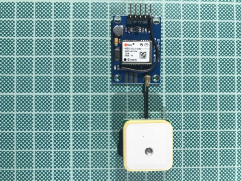
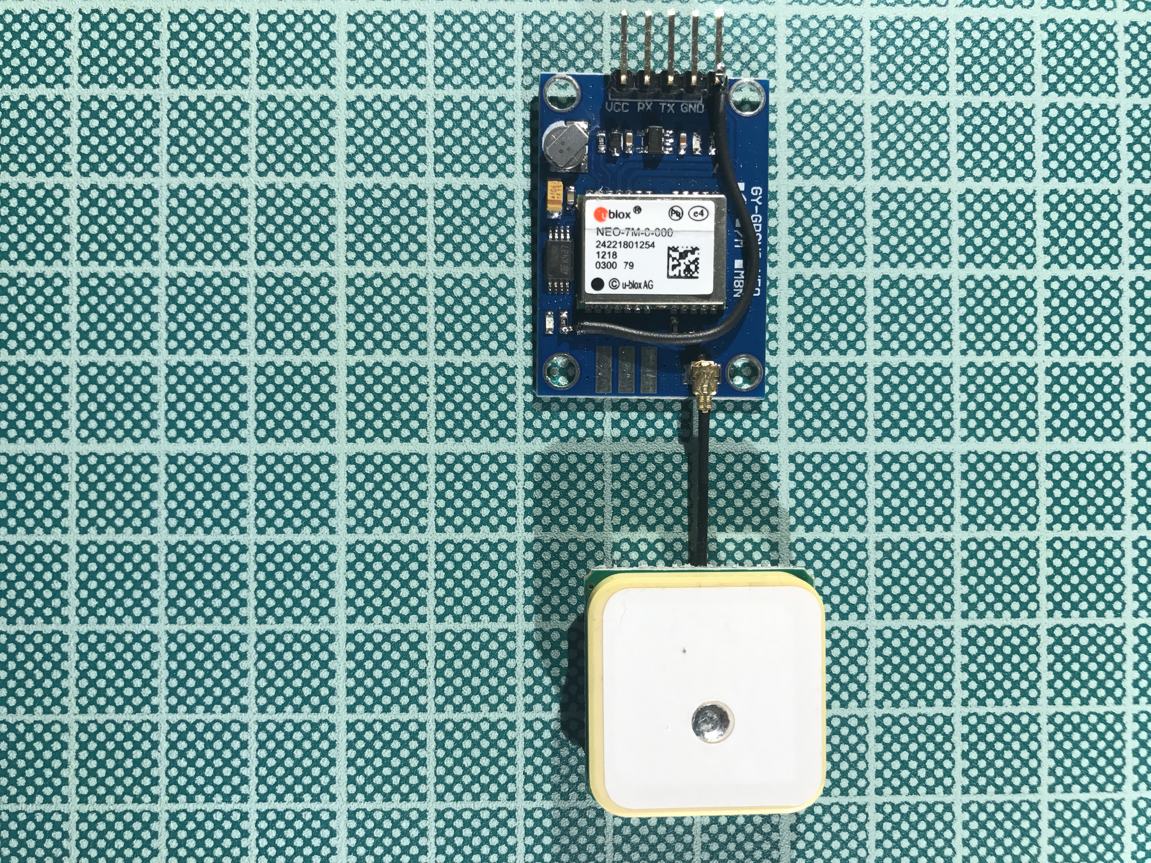
For my GPS locked Frequency Reference Standard 🙂 i bought a u-blox NEO-7M Module (uBlox Neo-7M GPS)
u-blox makes great GPS receivers and getting a module should speed up the breadboard design.
This modules comes without a PPS pin. This can be easily solved by using a 5-pin header (use a wire cutter to trim the 5 pin directly to the plastic) and a piece of wire connected to the on board led
ucenter
I run the board on 3.3V and i already had a 3.3V RS232 converter handy.
u-blox provides a tool called ucenter (used version 8.23)
GPS is already configured at 9600 bps
Start your ucenter
Receiver -> Port -> COM3 (replace with your com port)
Change your configuration to the below (for 10 MHz on PPS on locked and 5 Hz when unlocked)
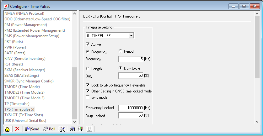
And press send
Jitter
First issue encounter was the jitter on the 10MHz. NEO-7M uses a 48 MHz crystal internally and it cannot be divided exactly for 10 MHz…
Scope outputs

And our favorite for 10 MHz…
I still don’t know if i should use a 10 MHz crystal as a filter and then a schmitt trigger to give a clean square wave output.
Use a ground plane for the ceramic antenna, it’s a huge difference on, a simple one side PCB will do the trick, place the ceramic antenna ontop
Loosing settings
The backup current needed for NEO-7M is 10μA. The capacitor selected on this board is a a XH414HG which has 30μAH capacity till it reaches the 2V… Seriously… max 2.5 hours disconnected from the power and you loose the settings created above… Solved by using a CR2032 and a diode
Using just the GPS for 10MHz output is a NO GO
Leave a Reply to DL6MBE Cancel reply